Specify and modify a data centre scenario
CactoSim provides a wealth of options to modify and adapt physical or logical data centre resources. This section of the user manual explains the individual building blocks used to define and manipulate various simulation scenarios in CactoSim. Users can combine those building blocks to fit the purpose of a specific data centre analysis.
Each subsection contains detailed step-by-step instructions supported by screenshots of the actual graphical user interface provided by CactoSim. The aim is to cover the functionality of core features of this CactoSim release as well as to introduce the general principle notion of cloud modelling using the provided tree editor interface. This section presents the building blocks in a typical usage order, from importing the models from the Runtime Model Storage to versioning of a model for later analyses.
Load a Data Centre Model from the Runtime Model Repository
The CACTOS models can be imported (loaded) from the CDO Runtime Model Storage by:
- Clicking in the Eclipse menu File -> Import shown in Figure 1
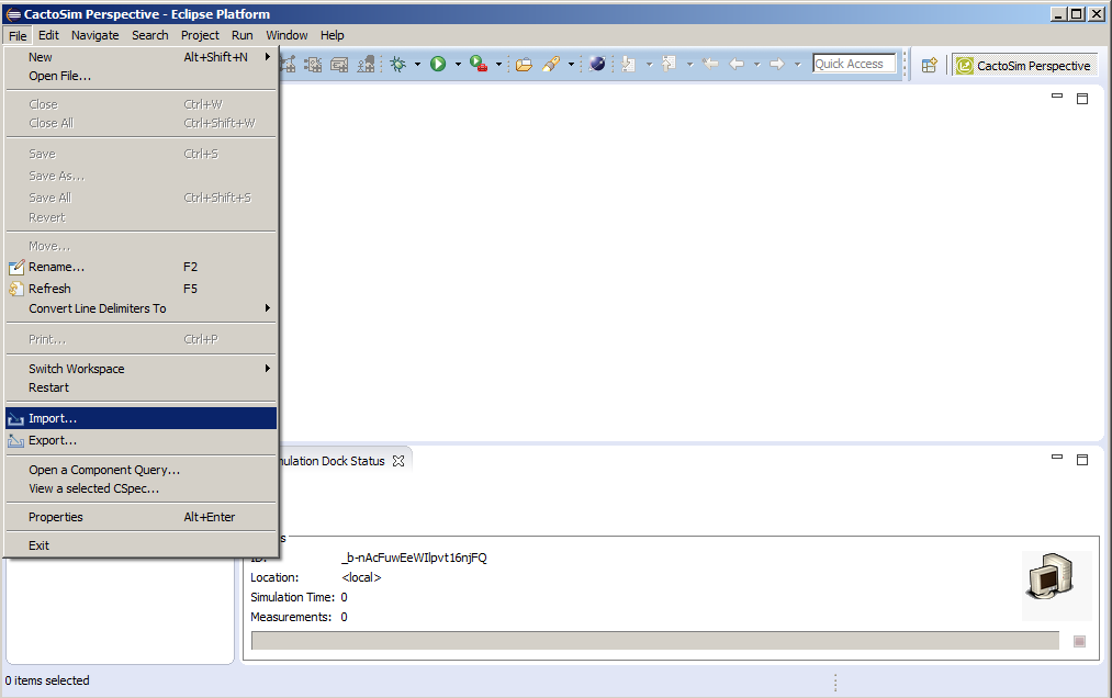 Figure 1: Load a Data Centre Model from the Runtime Model Repository - Import
- Then expanding the CactoSim folder and selecting the option Runtime Model Storage to Workspace (Figure 2). This action will trigger the CactoSim project creation wizard.
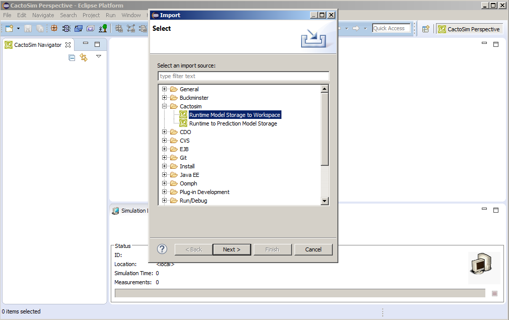 Figure 2: Load a Data Centre Model from the Runtime Model Repository – Select Wizard
- Next, provide the name for the project that will be created in the workspace, as shown in Figure 3.
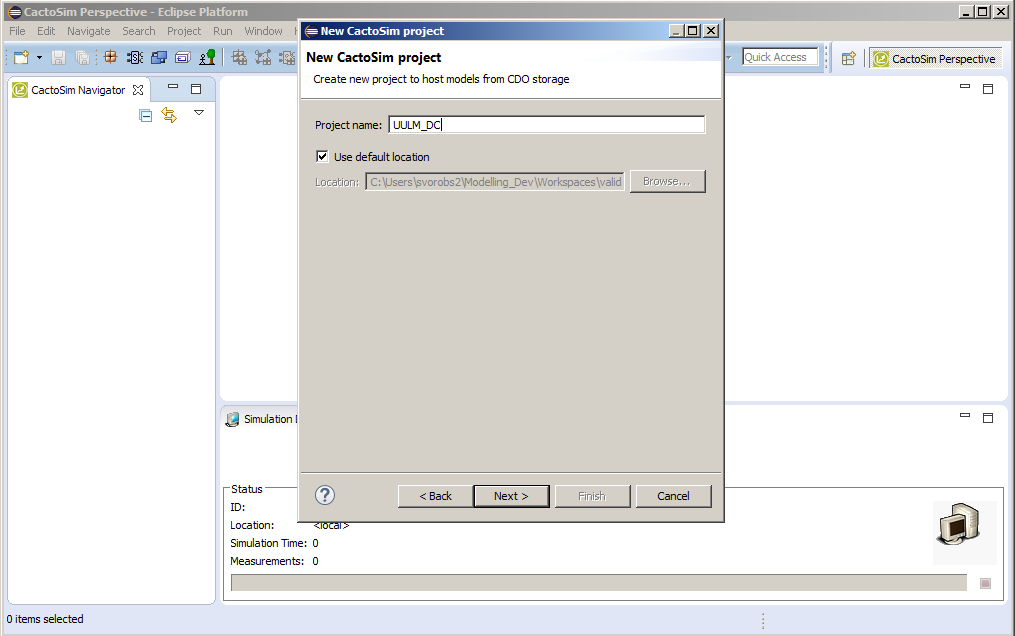 Figure 3: Load a Data Centre Model from the Runtime Model Repository – Name Project
- Then enter credentials for accessing the CDO Runtime Model Repository and click “Finish”, shown in Figure 4.
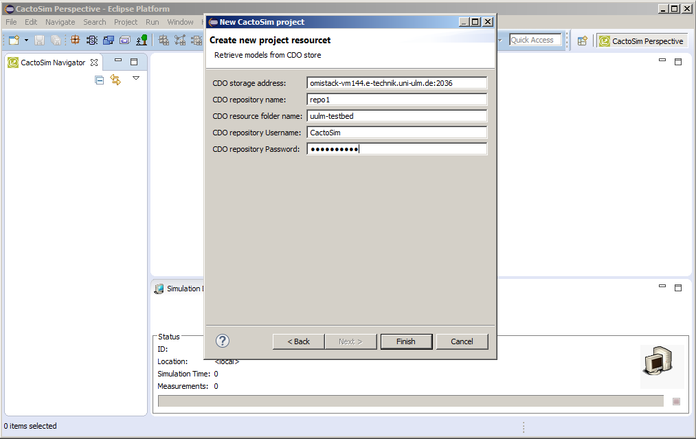 Figure 4: Load a Data Centre Model from the Runtime Model Repository - Credentials
- CactoSim will now connect to the server and fetch CACTOS models to the workspace folder. The models can then be viewed and edited in the resource tree viewer, shown in Figure 5.
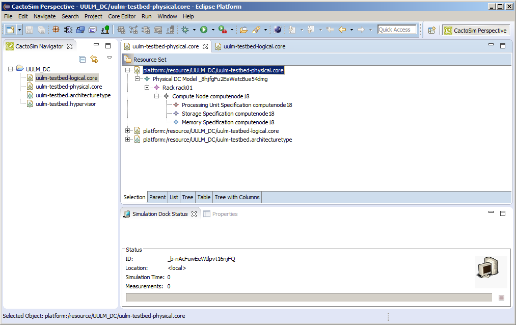 Figure 5: Load a Data Centre Model from the Runtime Model Repository – Model Access
Load a scenario specification from the prediction model storage
Once the models have been stored in the prediction model storage (see “Store a scenario specification in the prediction model storage”) they can be loaded and explored by standard versioning tools procedures.
Right-click the models folder under the Model Repository view and selecting the Checkout option, see Figure 6.
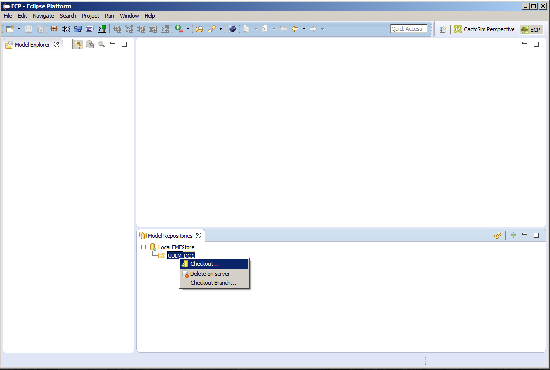 Figure 6: Load a Scenario Specification from the Prediction Model Storage - Checkout
Create a local project folder where the models will be placed by giving it a name, see Figure 7.
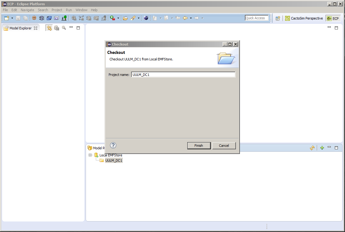 Figure 7: Load a Scenario Specification from the Prediction Model Storage – Create Project
- Once the models are checked-out they will appear in the model explorer window which is by default located on the left hand side, see Figure 8.
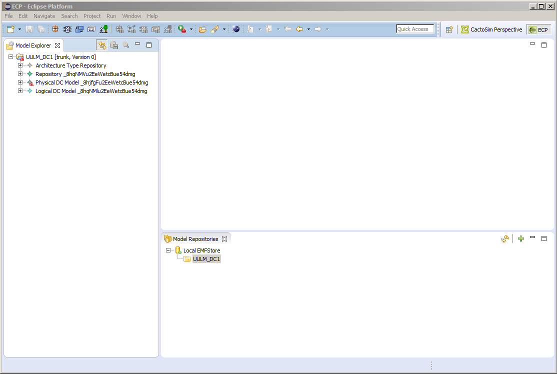 Figure 8: Load a Scenario Specification from the Prediction Model Storage – Model Explorer
Creation of Virtual Machines
The creation of VMs is required for scenarios with additional VMs deployed in the data centre. Those VMs can be based on existing VMs in the Infrastructure models or completely customized to fit the behaviour of VMs for any given scenario.
In order to create a Virtual Machine model element, it firstly has to have a valid VM Image entity to be linked with. Once the models are retrieved using instructions from “Load a Data Centre Model from the Runtime Model Repository”:
- Double click the logical data centre model file in the workspace to open it. Next right-click the top Logical DC Model element and from the menu select New Child -> VM Image, as shown in Figure 9.
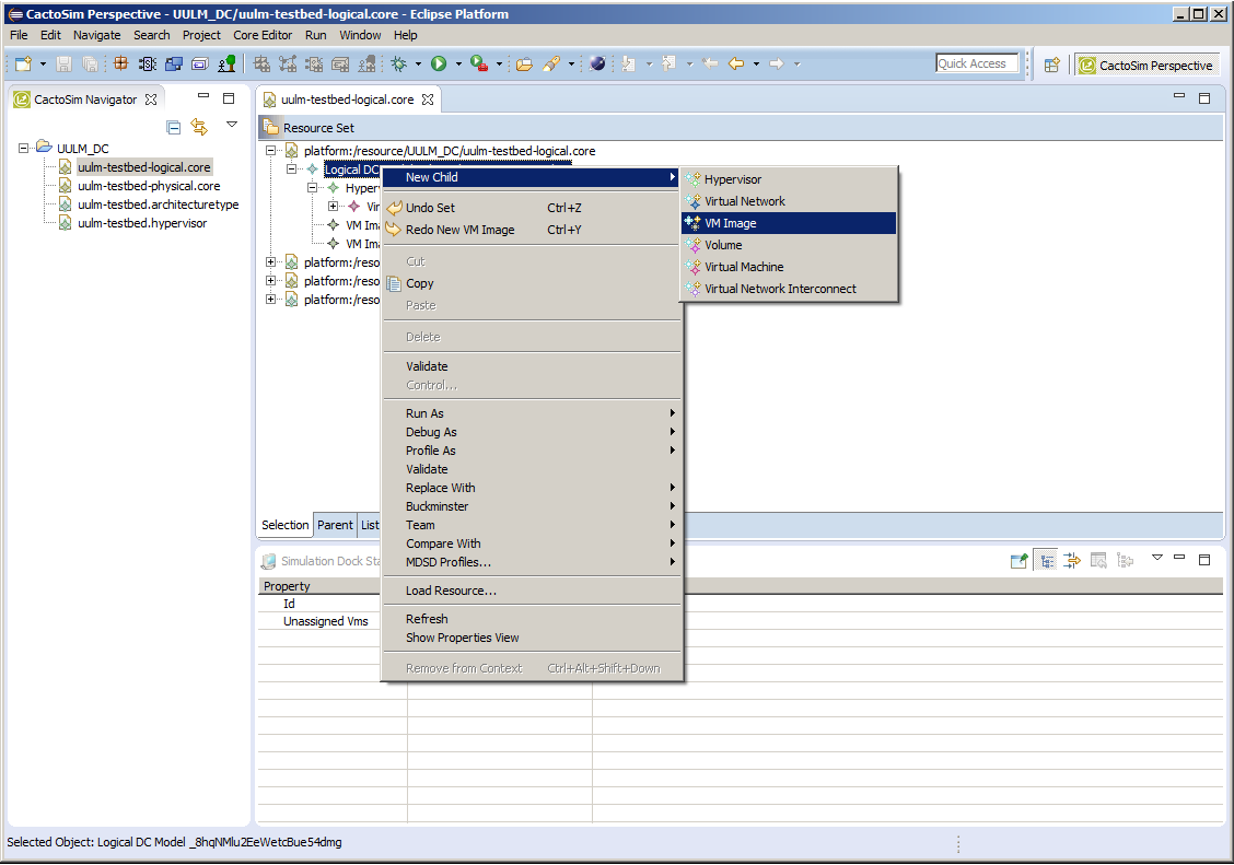 Figure 9: Creating of VM - VM Image Instance
- Define properties of a newly created VM Image entity under the Properties view, as shown in Figure 10.
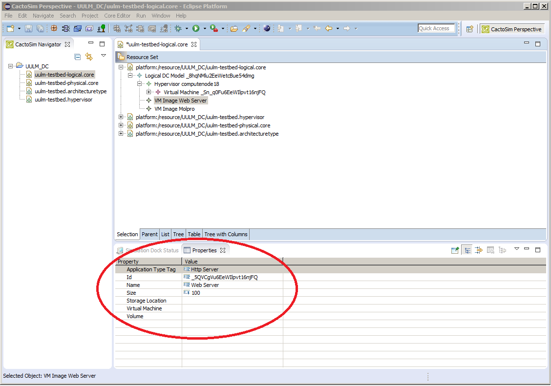 Figure 10: Creating of VM –VM Image Properties
- Next right click on the Hypervisor entity and select New Child -> Virtual Machine menu, shown in Figure 11.
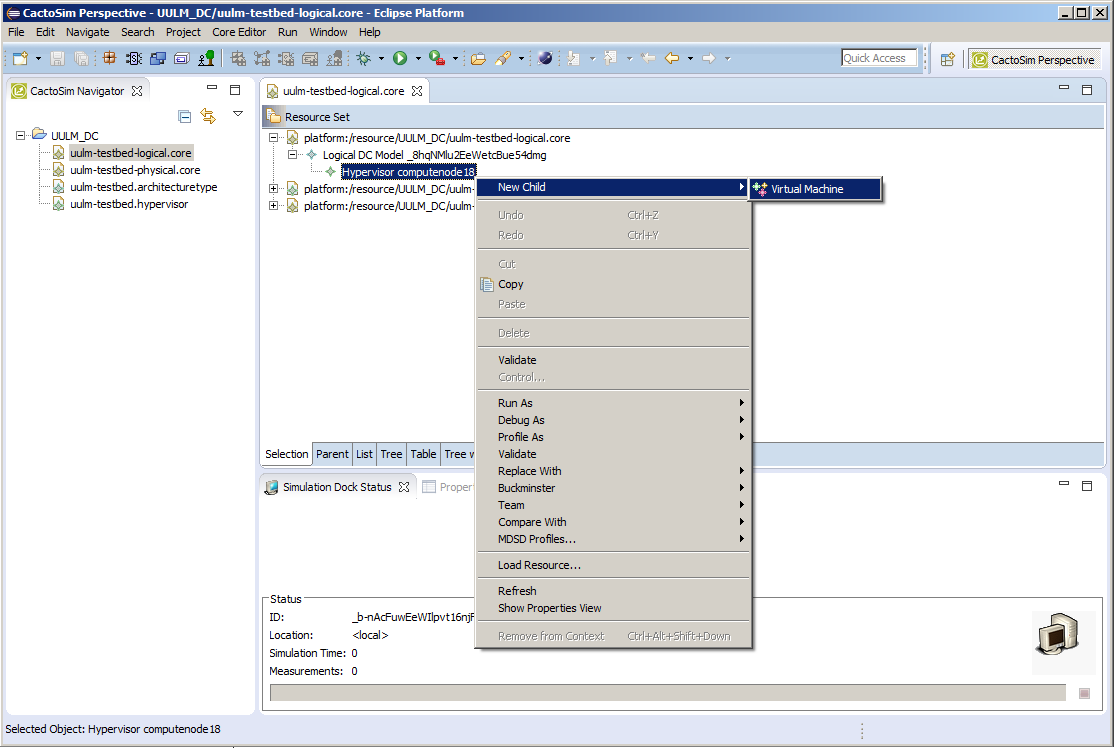 Figure 11: Creating of VM –New Instance
- Further following the same principle right click on the created Virtual Machine instance and create VM Image Instance, Virtual Memory, Virtual Processing Unit and application model. A sample configuration is shown in Figure 12.
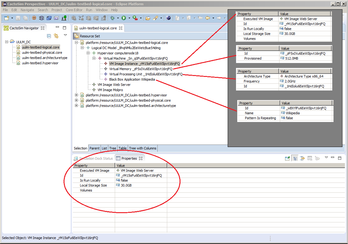 Figure 12: Creating of VM - Configuration
Creation of Compute Nodes
Adaptation scenarios can require the adding of new compute nodes to the simulated data centre. Compute nodes belong to racks, which are contained in the physical data centre model. In order to create compute node elements, the following steps need to be performed:
- Right-click on the Rack element which should contain the new node, select New Child -> Compute Node, as shown in Figure 13.
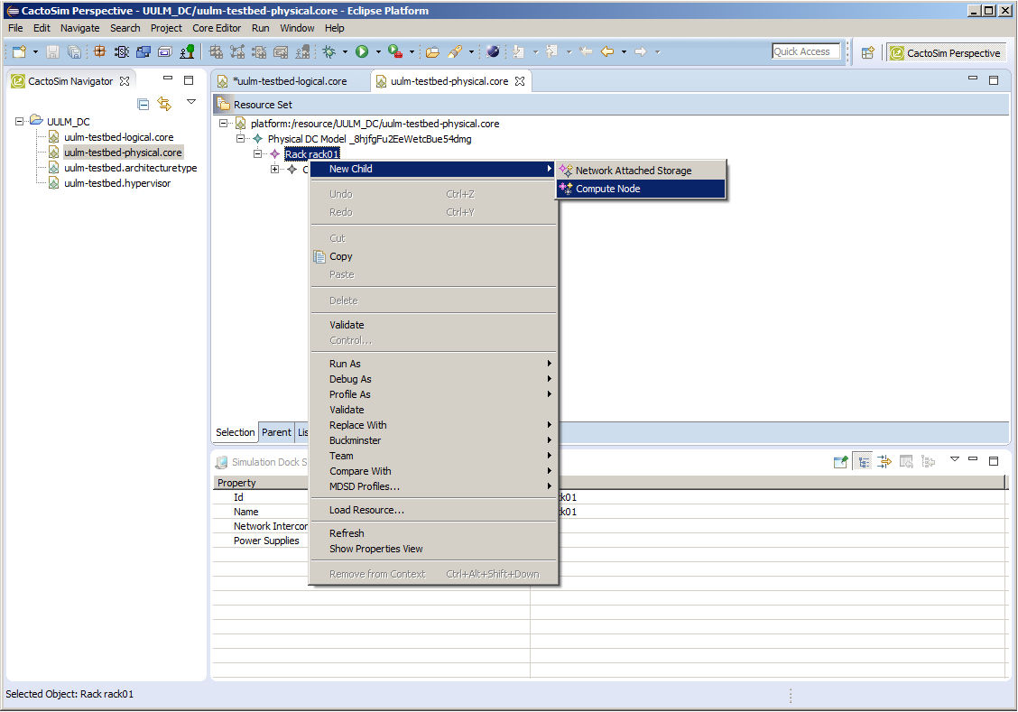 Figure 13: Creation of Compute Nodes – New Entity
- In the newly created Compute Node entity properties fill in the required attributes. Right click on the newly created node and create as a child Processing Unit Specification, Storage Specification and Memory Specification. Example configuration options are shown in *Figure 14.
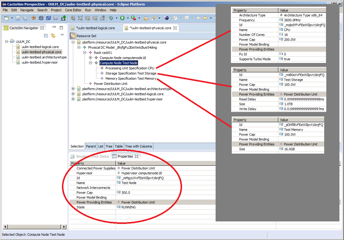 Figure 14: Creation of Compute Nodes – Configuration Properties
Assignment of VMs to Compute Nodes and Moving of VMs
In order to assign a VM to a compute node it needs to be linked to a hypervisor that is running on that node. Note that each physical node can only have one hypervisor. You may want to re-use an existing hypervisor and move a VM there by Cut-and-Paste or via Drag-and-Drop. In the section Creation of Compute Nodes it was shown how to create a new Compute Node entity. In this section we will create a Hypervisor and move a VM to it. To begin:
- Open the logical data centre model and right-click on the Logical DC Model entity. Select the New Child -> Hypervisor option, as shown in Figure 15.
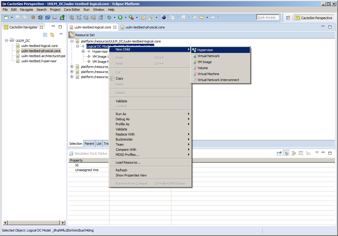 Figure 15: Assignment of VMs to Compute Nodes and Moving of VMs – New Hypervisor
- The newly created Hypervisor element under its properties at the Node attribute will have a dropdown list with all available nodes where it can be linked, as shown in the Figure 16. The appropriate node instance must be selected to create a link with physical data centre representation.
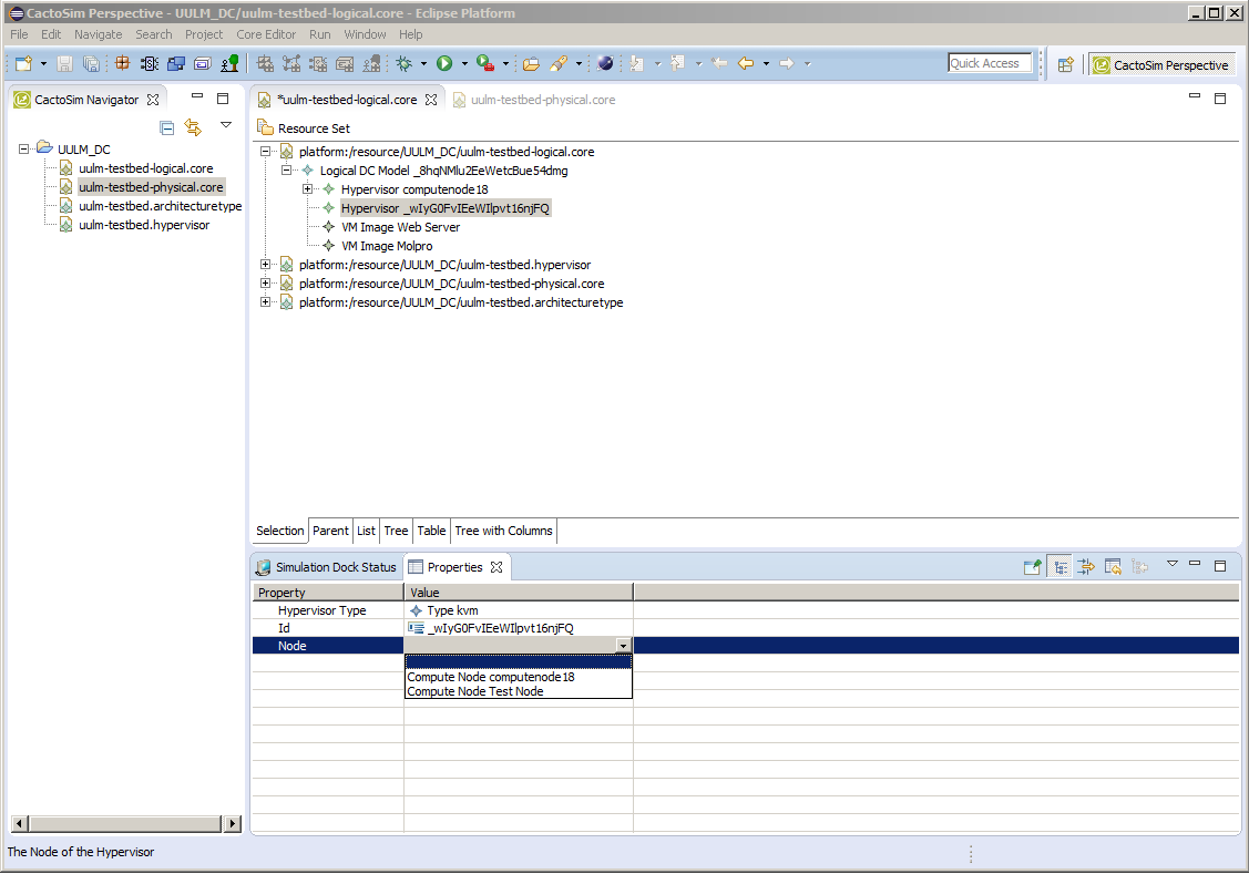 Figure 16: Assignment of VMs to Compute Nodes and Moving of VMs –Node Selection
- Finally the Virtual Machine element can be moved to new hypervisor by drag-and-drop functionality, as shown in Figure 17.
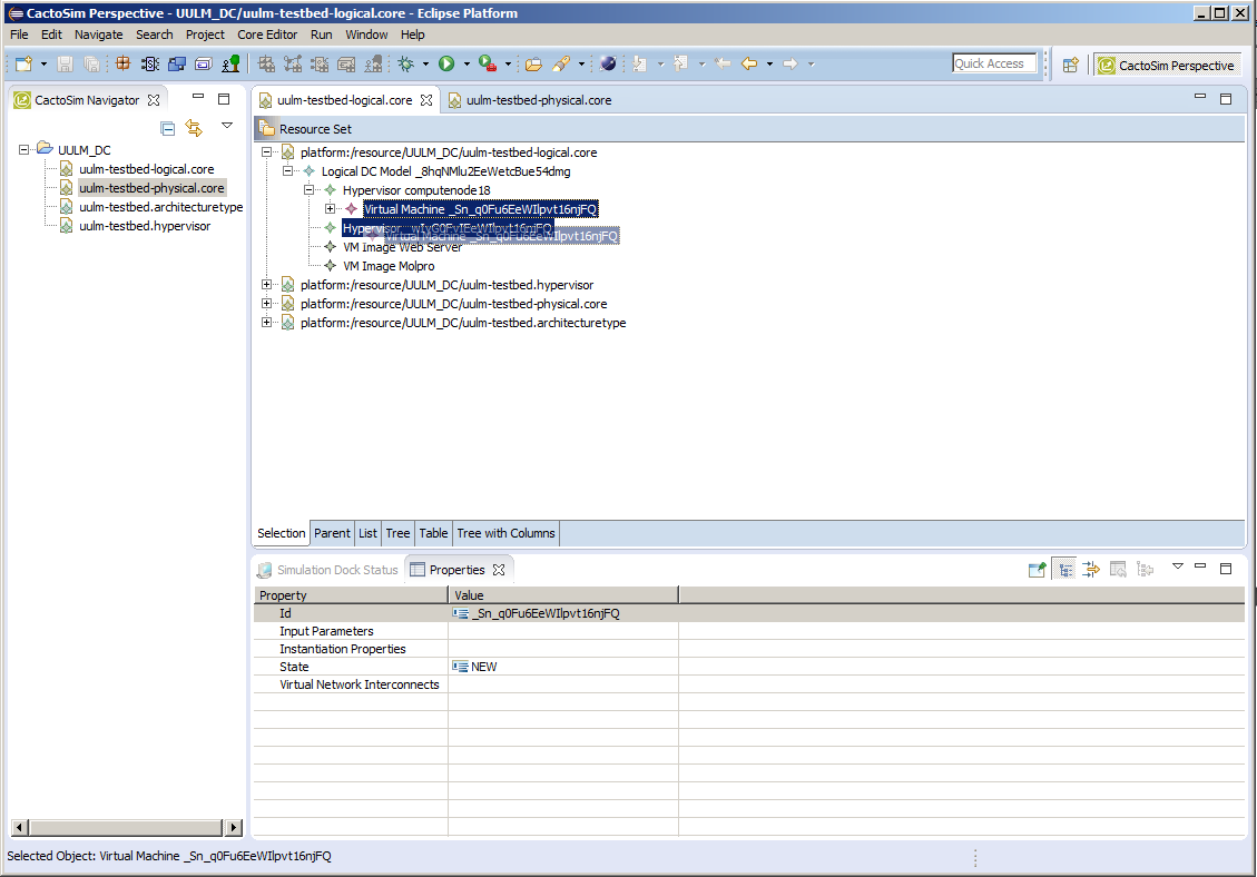 Figure 17: Assignment of VMs to Compute Nodes and Moving of VMs –VM Relocation
Store a scenario specification in the prediction model storage
Once the datacentre models have been created or downloaded from the Runtime Model Storage, it is recommended for them to be stored using a versioning control system such as GIT [13] or Subversion [15]. The serialised models are written in the XML Metadata Interchange (XMI) format which is suitable for tracking changes and merging content. Information on how to use the suggested versioning systems can be found in freely available “Pro GIT” book [14] and “Version Control with Subversion” book [16].
Simulation scenarios can also be loaded from the Runtime Model Storage directly to the local EMF Storage [17]. To perform this action:
- Click in the general Eclipse menu File->Import->Runtime to Prediction Model Storage
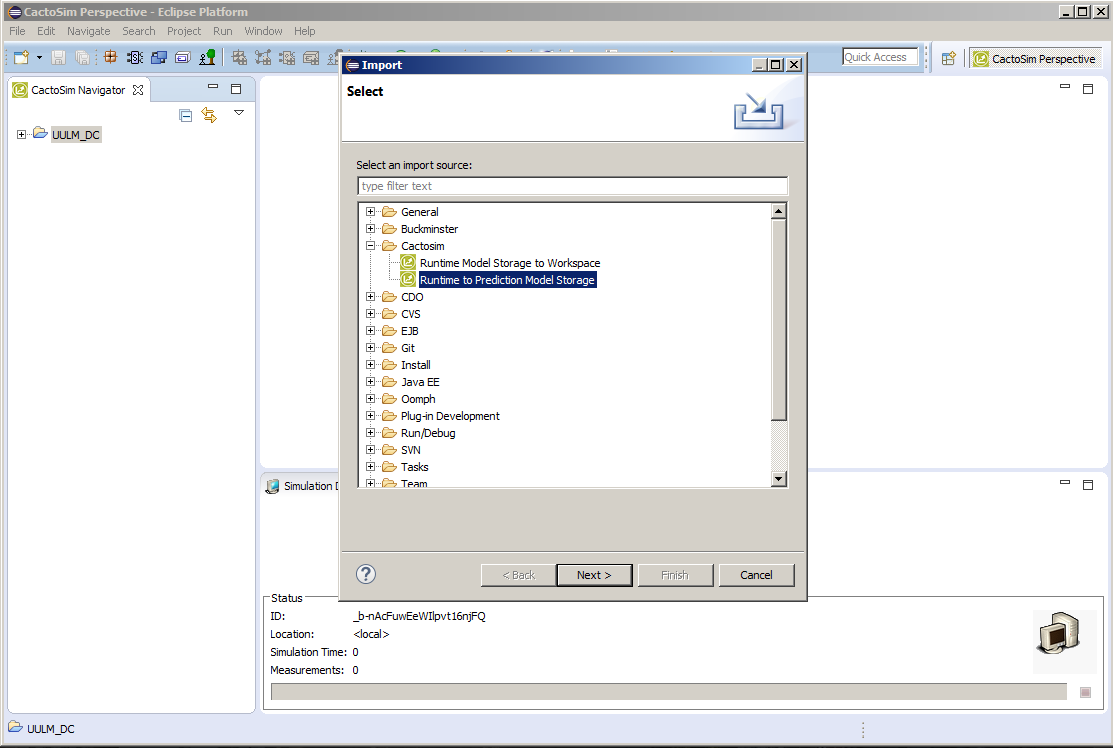 Figure 18: Store a Scenario Specification in the Prediction Model Storage – Wizard Selection
- Enter Runtime Model Storage login credentials together with server address attributes.
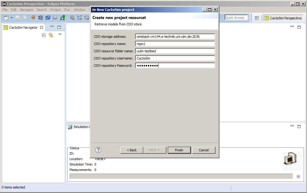 Figure 19: Store a Scenario Specification in the Prediction Model Storage – Credentials
-Specify the name of the project that is to be created in the local storage
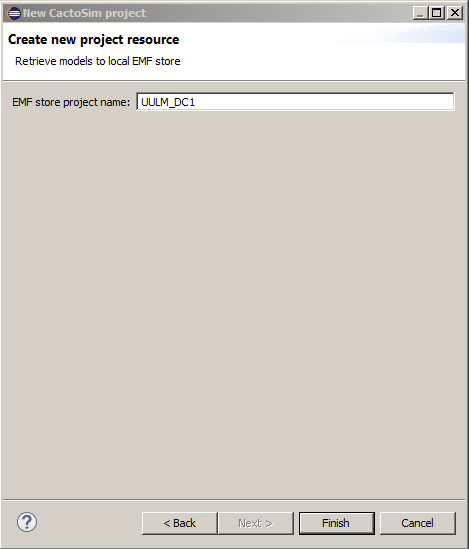
Figure 20: Store a Scenario Specification in the Prediction Model Storage – Project Name
- After the models have been imported, they can be viewed by switching to the ECP perspective in Eclipse. The perspective selector is shown in Figure 21.
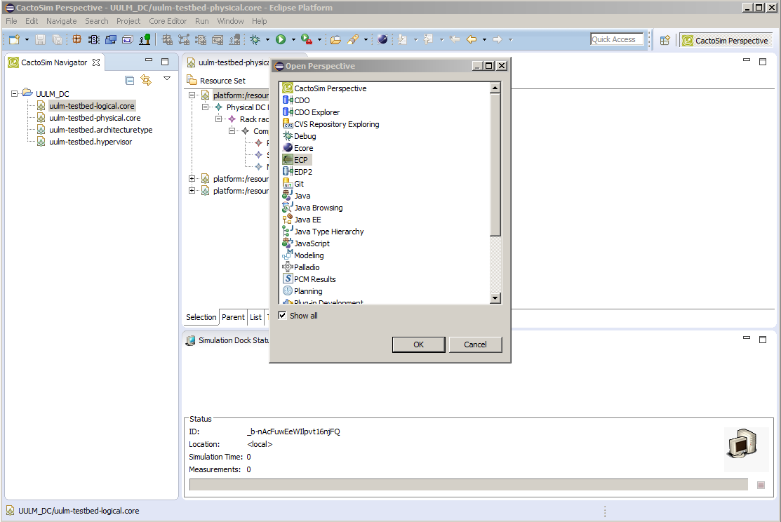 Figure 21: Store a Scenario Specification in the Prediction Model Storage – ECP Perspective
- The full list of persisted models is provided under the Model Repositories tab, shown in Figure 22. To use the saved models please refer to the instructions in Load a scenario specification from the Prediction Model Storage.
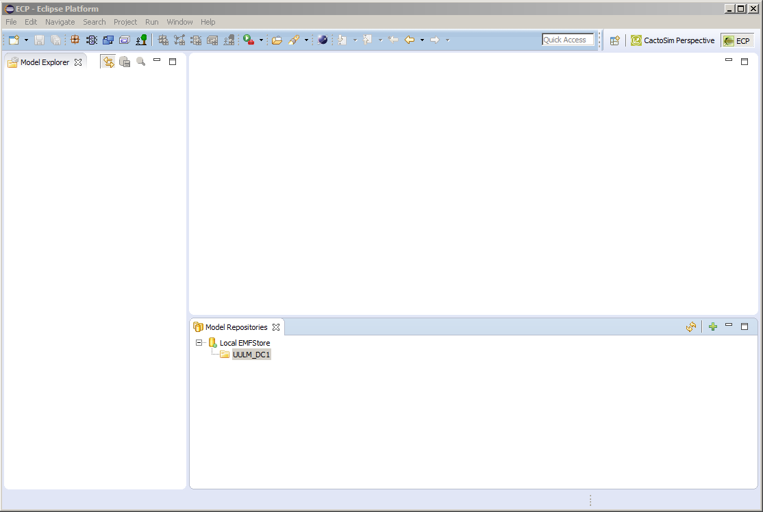 Figure 22: Store a Scenario Specification in the Prediction Model Storage – Model Repository